Link Trainer
Aircraft Details
- Model: Link ANT-18
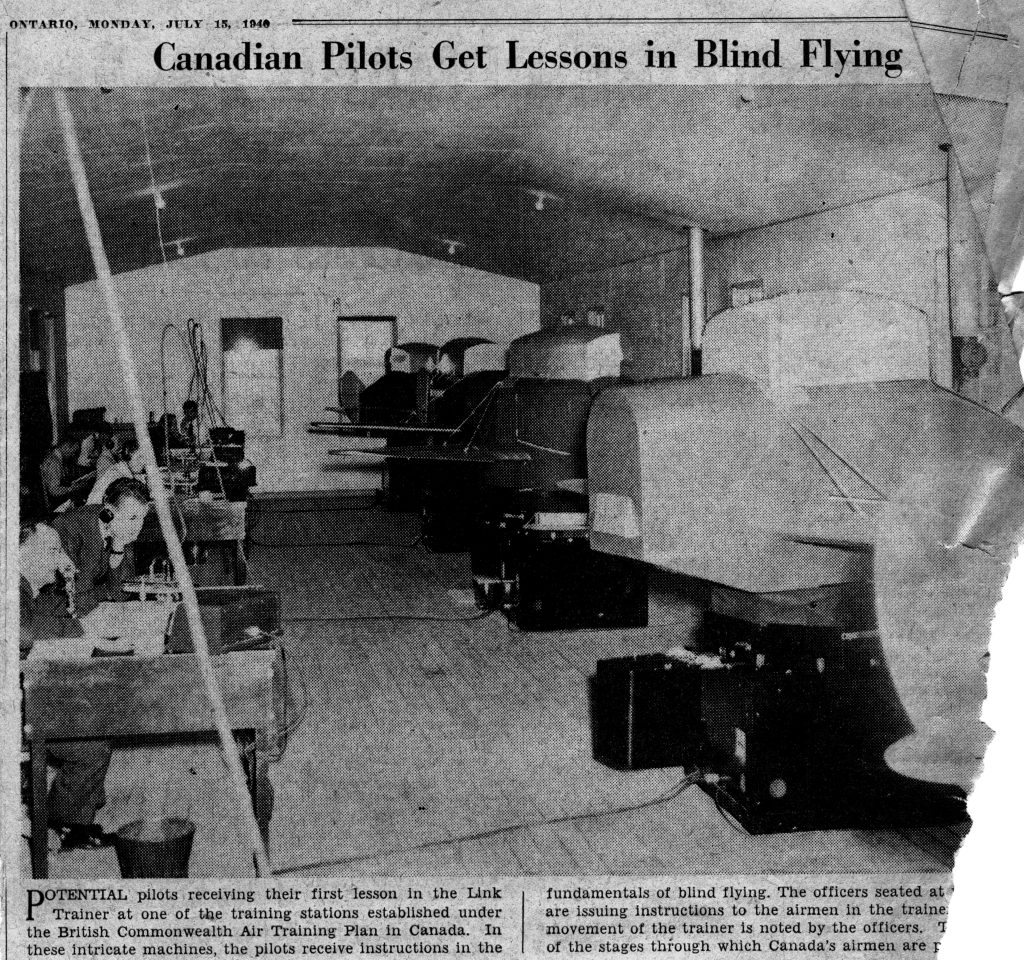
- Taught pilots to fly in darkness and poor weather
- Flight simulator also known as the “Blue Box” and “Pilot Trainer”
- Because Flying lessons were so expensive, Edwin Link got the idea of how to shorten expensive flying lessons so Student Pilot could learn rudimentary piloting skills
Trainer Description
- Taught pilots to fly in darkness and poor weather
- Flight simulator also known as the “Blue Box” and “Pilot Trainer”
- Because Flying lessons were so expensive, Edwin Link got the idea of how to shorten expensive flying lessons so Student Pilot could learn rudimentary piloting skills
- In 1928, Edwin Link left his father’s Organ building business to develop a “Pilot Trainer”
- Used knowledge and skills learned from his expertise in air-driven pianos and pipe organs
- Used organ parts and compressed air to build the first flight simulator
- Designed the trainer using suction through fabric bellows to cause motion
- Organ bellows and a motor mounted on a pedestal provided the means for the trainer to pitch, roll, dive and climb as the student “flew it”
- In 1931 Link received a patent on his Pilot Maker training device
- Most of first sales were to amusement parks – little interest by the flying community
- by 1934 – Army Air Corps bought 6 to train pilots to fly at night and bad weather
- Second customer was the Japanese Imperial Navy in 1935
- Need for Pilots with instrument training increased in World War II
- Link delivered 6,271 Link Trainers to the Army and 1045 to the Navy – More than 500,000 US pilots were trained using a Link Trainer
- Also used by 35 foreign countries
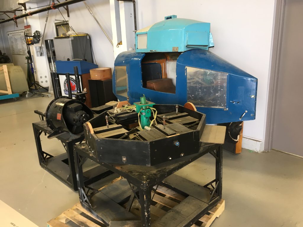
Link Trainer Restoration

Hardware Description
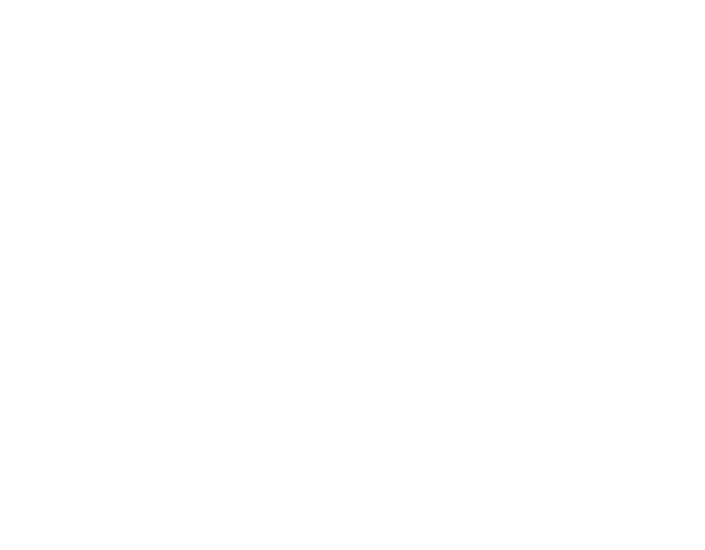
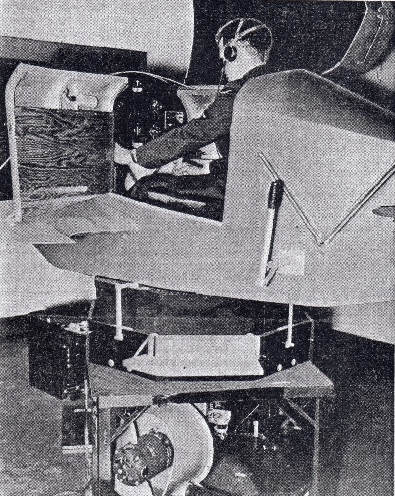
Student Pilot Training Position (Cockpit)
- Wooden box about the shape of a cockpit and forward fuselage section
- Connected via a universal joint to a base
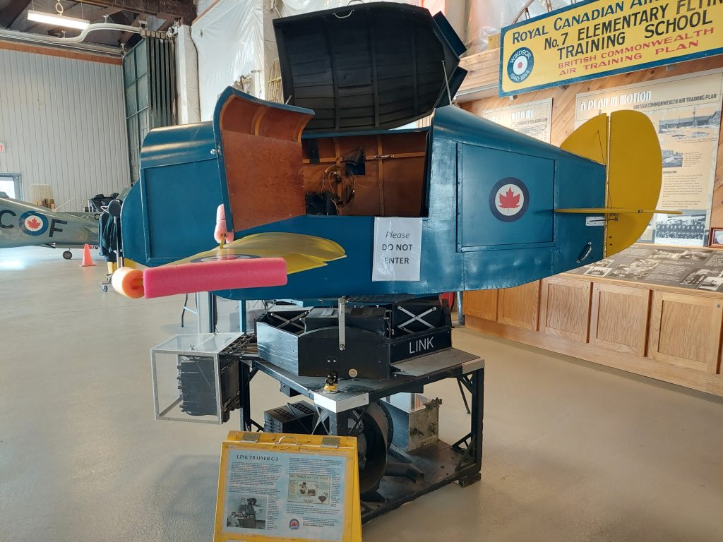
- Cockpit contains:
- a single pilot’s seat
- primary and secondary aircraft controls
- full suite of flight instruments.
- Motion Base contains:
- Several complicated sets of air-driven bellows to simulate movementA vacuum pump which both drives the bellows and provides input to a number of aircraft instruments
- A Telegon Oscillator, which controls the remaining instruments.
- One under each of the 4 corners of the cockpit) controls movement in the pitch and roll planes.
- A very complicated set of bellows at the front of the cockpit controls movement in the yaw plane. This complex set of 10 bellows, two crank shafts, and various gears and pulleys comprised the turning motor. This motor could turn the entire cockpit in continuous 360 degree circles. This was possible since a series of electrical slip ring contacts in the lower base compartment, supplied electrical continuity between the cockpit and the base.
- A third set stimulates vibration such as stall buffet. Both the trainer and the instructor’s station are powered from standard 110VAC/240VAC power outlets via a transformer, with the bulk of internal wiring being low voltage. Simulator logic is all analog and is based around vacuum tubes.
Instructor Station
- a large map table
- a repeated display of the main flight instrument
- a moving marker known as a “crab”. The crab moves across the glass surface of the map table plotting the pilots track.
- The pilot and instructor can communicate with each other via headphones and microphones.
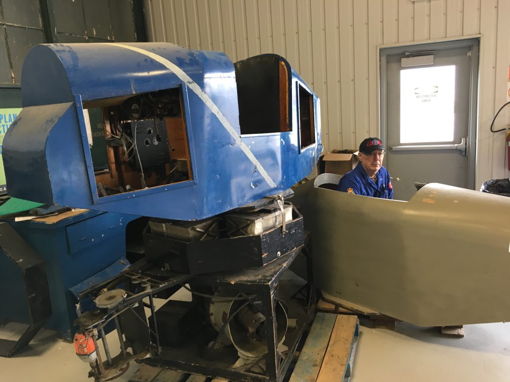
Our Museum’s Link Trainer
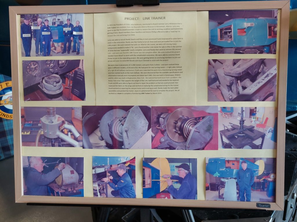
In 2015 the President of CH2A, John Robinson, mentioned to Board member Larry Whitmore that a Link Trainer was available from the Reynolds-Alberta Museum in Wetaskiwin, Alberta. Larry was quick to say that he would assemble a team to restore the Link to working condition and looked into getting it here. Board members Dave Hamilton and Dennis Phillips offered to take a ‘road trip’ to recover the Link and bring it to CH2A.
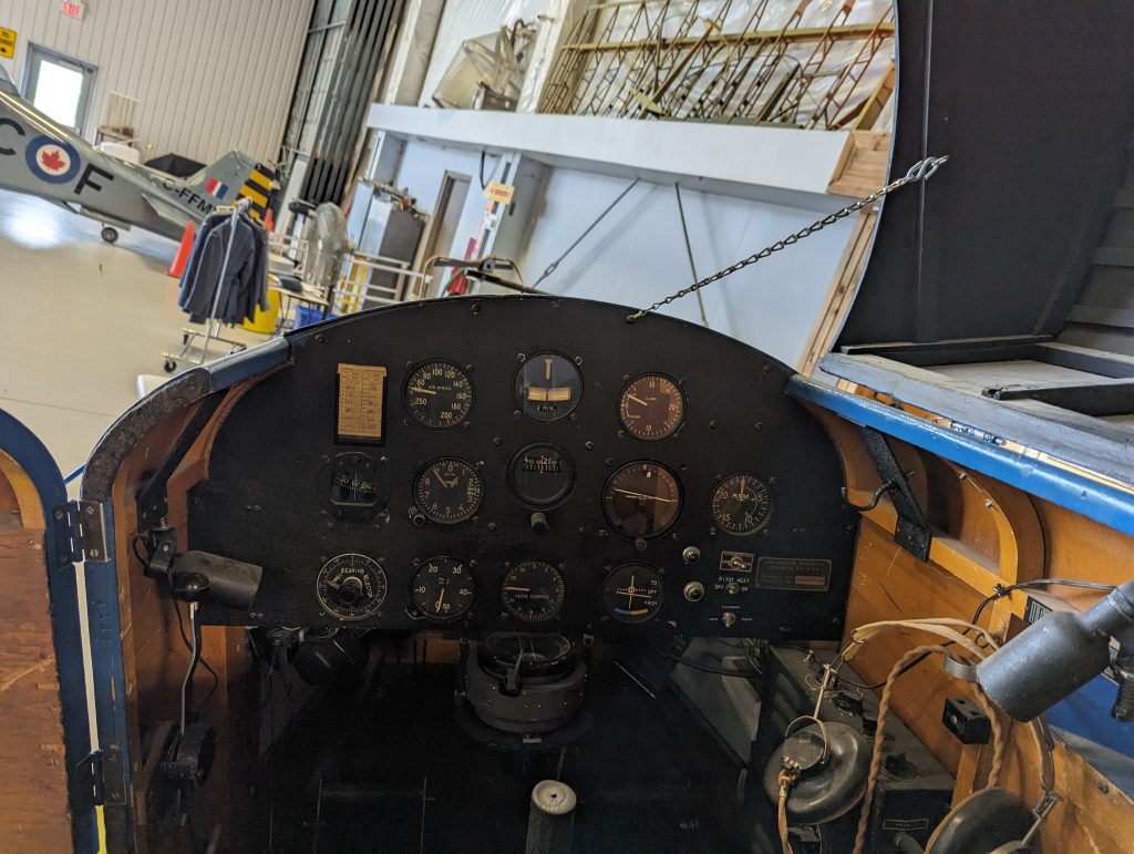
Larry was able to recruit Randy Swarts and they in turn convinced Frank Greenwood to come back to assist in the restoration. Randy saw Dan Garbut at an air show and soon persuaded Dan to join the LINK project. We soon realized that with our Alberta Link trainer, we were still missing many components needed to make it ‘fly’. Larry found another Link trainer for sale in Ohio in the summer of 2016 that was ‘supposedly’ nearly complete. Larry and Randy then went to retrieve this second Link- and soon saw that this LINK Trainer was not complete either. We soon realized this project needed ‘more blood’ to assist with the complicated restoration. We were able to convince David Porter to join in the expanding project. We were getting better at convincing members to join our group and soon recruited Bill Woods and Joyce Cherwak to assist with the project.
We were now in possession of 2 LINK trainers- and parts from 2 others – and soon realized these were 2 different models, a C-3 and a C-5. We had parts for one turning motor – 2 right sides instead of a right & left bellows mechanism. Frank soon reworked the parts into a functioning turning motor and then started work on the main bellows. We soon discovered that the available specifications and information manuals were incomplete and dated April 1943. One was built in Gananoque, Ontario and the other was built in Binghamton, New York. We noticed that both bases had a problem – the heavy ‘iron cross’ that supports the weight of the Link, had fractured and needed to be repaired. Frank and Bill were able to figure out how to repair the problem so that we could proceed. Dan replaced the fabric on the wings and worked on replacing the complicated wiring for the trainer. David worked on repairing the vacuum motor and re-wiring as well. Randy made the tail/rudder assemblies and painted the trainer. Joyce re-upholstered the seat to complete the project.
We all worked as a team to complete a functioning LINK Trainer by March 2019.

Application and Uses
Instrument Flying Training: The primary application was to teach pilots to fly solely by instruments, particularly at night or in bad weather conditions, without visual reference to the outside world.
Cost-Effective Training: Allowed for safe and economical ground-based training, significantly reducing the cost and risks associated with actual flight time.
Basic Flight Maneuvers: Could simulate various flight maneuvers, including climbs, dives, turns, banks, and even spins, responding to the pilot’s controls with realistic “feel.”
Instructor-Controlled Scenarios: An instructor at a separate console could introduce conditions like turbulence, wind changes, and instrument malfunctions, while a mechanical pen tracked the student’s simulated flight path on a map.
Pilot Assessment: Used at initial flying training schools to test coordination and aptitude for flying, with failure often ending a student’s pilot career.
Skill Maintenance: Experienced pilots also used Link Trainers to maintain their instrument flying skills.
Familiarization with Routes: Allowed pilots to practice navigating over specific routes using radio aids before flying them in real aircraft.